Finally, we finished the design of FSM-55.
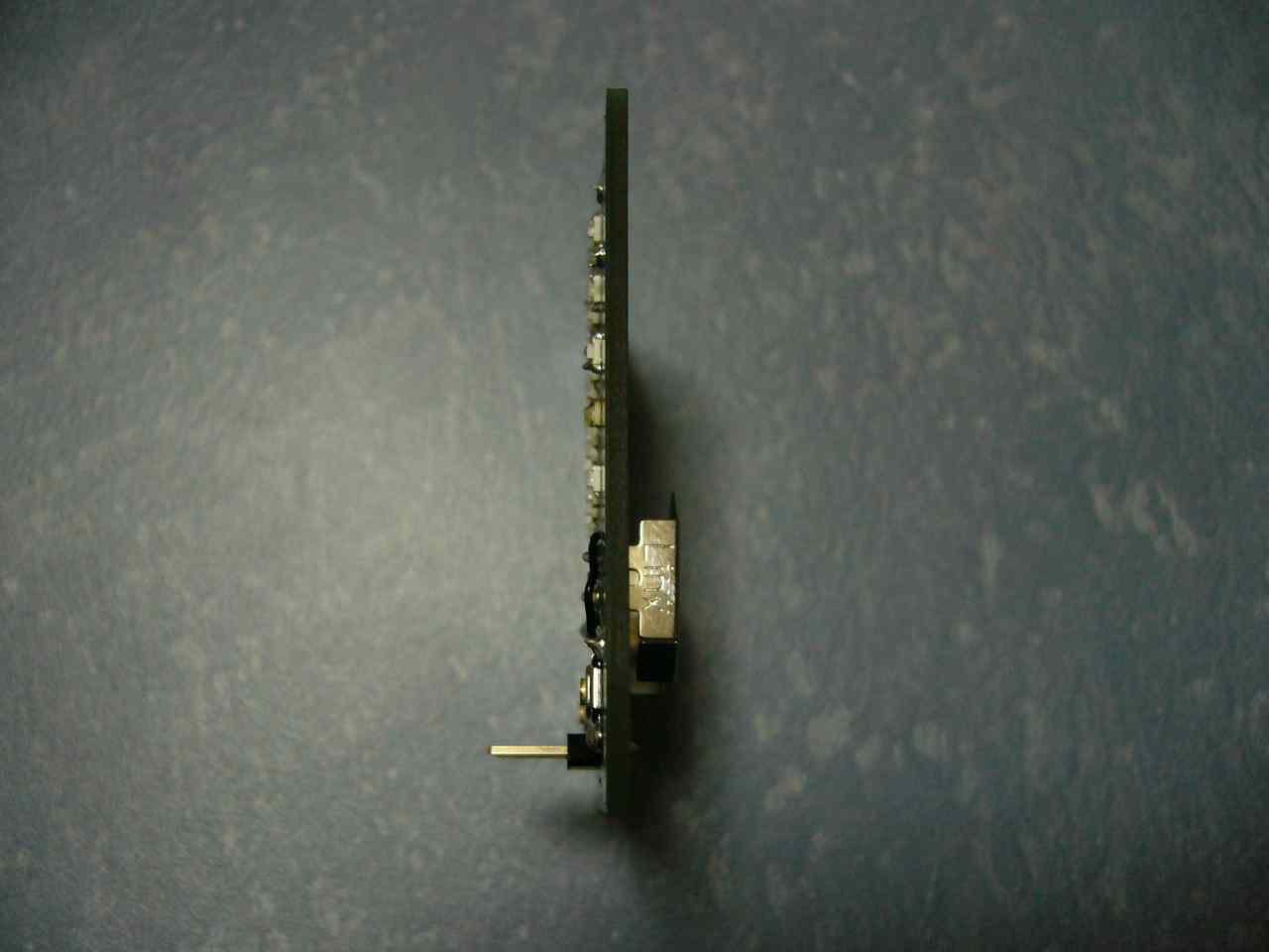
Its size is about 5cm x 5cm, with 5x5 LED matrix, 5 resistors and 5 capacitors.
When you pronounce it, please say, F-S-M "Go" "Go", since "Go" is the pronunciation of 5 in Japanese.
Components of FSM-55
- MCU: STM32F030F4
- Cell battery holder: BAT-HLD-001-THM
- LED: LG R971-KN-1
- Tactile switch: SKQGAFE010
- 5 Resistors
- 5 Capacitors
STM32F030F4
MCU is one of Cortex-M0 based ARM by STMicroelectronics. It runs at 48MHz and has 16KB flash ROM and 4KB RAM.
BAT-HLD-001-THM
For battery holder, we choose BAT-HLD-001-THM.
LG R971-KN-1
For LED, we choose LG R971-KN-1.
SKQGAFE010
For tactile switch, we choose SKQGAFE010.
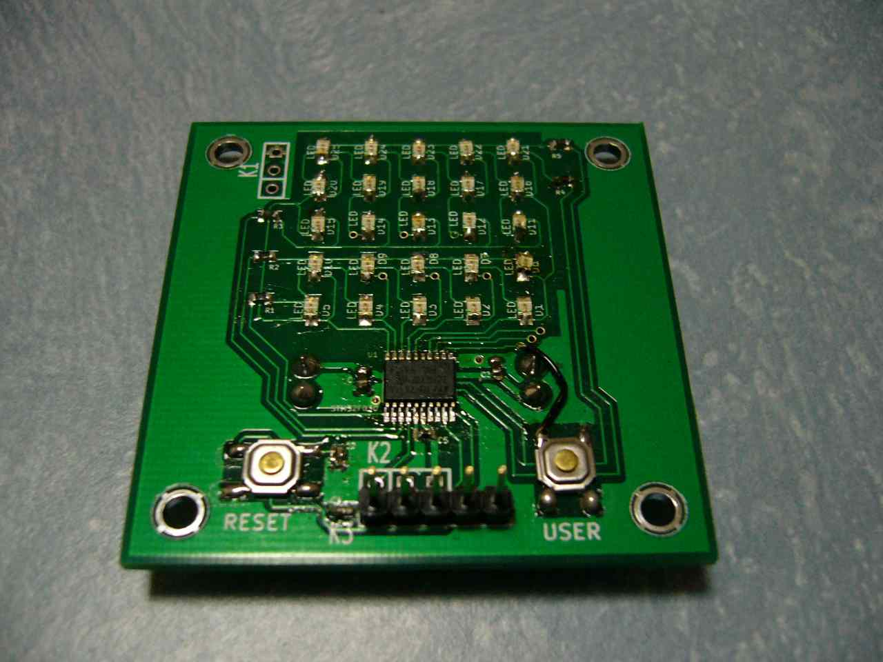
Prototype of FSM-55
Since this prototype had an error, I put a jumper (black wire). You can see that this prototype has debug port connector (K3).
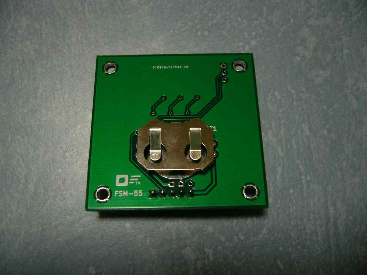
My plan is manufacturing a board with no battery holder or any connectors (but MCU, LEDs, Resistors, Capacitors, and Buttons) and ask users to put the battery holder (and possibly debug port connector, etc.).