We need to specify the test plan to manufacture the board. In order to encourage designing and manufacturing by yourselves, we show our test plan for Flying Stone Mini 55 here.
As of August 2014, free software tool to program MCU's flash ROM is not yet ready (for reset signal control, specifically). Thus, We use the vendor supplied tool for SWD debugger.
Introduction
FSM-55 (Flying Stone Mini 55) is a small board with 5x5 LED matrix and a MCU. Since it has 25 (5x5) LEDs within the size of 5cm x 5cm, it has "55" in its name. Its a kind of starter kit for beginners. Note that "55" sounds like "Go! Go!" in Japanese.
Most starter kits are designed by MCU vendors and those kits tend to have many features, so that people can test various features of MCU.
FSM-55 is not for testing various features of MCU, but to enjoy lower level programming and/or to enjoy building own PCB by extending its PCB design. Its major and only feature is 5x5 LED matrix.
FSM-55 uses STM32F030 as MCU. It runs at 48MHz, and the architecture is a version of ARM, named Cortex-M0.
On FSM-55, there are two button switches (RESET and USER), and three connectors (K1, K2, and K3). K1 and K2 are extension ports for users. We only use K3 in our test plan.
The K3 connector is for SWD port (Vdd, SWD-IO, SWD-CLK, nRST and GND). Through Vdd and GND, we supply power to the board. nRST is to drive reset signal of MCU. SWD-CLK and SWD-IO are signals to debug MCU, and we use it to program MCU's flash ROM, as well.
Test Theory
With the SWD debugger (ST-Link/V2), we flash the firmware into MCU. We use command-line (CLI) utility named ST-LINK_CLI.exe from Command Prompt Window. The filename of our firmware file is: hacker-emblem.hex.
We invoke the command from the command line prompt window. When executed, the utility control the SWD debugger.
After successful invocation of ST-LINK_CLI.exe, the demonstration program runs on the board. At the start, its mode is to display Conway's Glider in Action (have a look at: Give a hacker 5x5 space or more for an animated GIF (direction is different, though)). When you push USER button, all 25 LEDs emit light, and button released, it changes its mode to display scrolling text of "HAPPY HACKING!". Pushing RESET button, it starts from the beginning (of the Glider).
Test Tools
Hardware: PC, ST-Link/V2 with Mini USB Cable, wires to connect the board
Software: Driver for ST-Link/V2, Utility for ST-Link/V2
Preparation
Firmware HEX file
Copy the file hacker-emblem.hex to PC. In the test procedure, we assume that it's at: Desktop\hacker-emblem.hex
Vendor tool
From the vendor site (ST.COM), driver and utility can be downloaded. The page URL is:
http://www.st.com/web/catalog/tools/FM146/CL1984/SC720/SS1450/PF251168
In the section of "Related Tools and Software" of the page, there is a table.
| Part Number | Description |
| STSW-LINK003 | ST-LINK/V2 USB driver for Windows 7, Vista and XP |
| STSW-LINK004 | STM32 ST-LINK utility |
| STSW-LINK005 | ST-LINK/V2 firmware upgrade |
| STSW-LINK006 | ST-LINK/V2 USB driver for Windows 8 |
Download those files and install them (This installation procedure is only required once for a PC).
- STSW-LINK005: ST-LINK/V2 firmware upgrade
The firmware of your ST-Link/V2 should be up-to-date. Download this to check the version of the firmware and if it's not up-to-date, upgrade the firmware.
- STSW-LINK003 or STSW-LINK006: ST-LINK/V2 USB driver
Install driver for ST-Link/V2.
If there is another device driver for "STM32 STLink" installed, disable it (or uninstall it).
- STSW-LINK004: STM32 ST-LINK utility
Install ST-LINK utility. Version should be 3.4 (or later).
If version is 3.3, please remove the word "LPM" from the command line below. Version 3.3 doesn't support this feature (but it just works).
Test Procedure
Hardware Connection
- Connect ST-Link/V2 with Mini USB cable to PC.
- Connect ST-Link/V2 and FSM-55
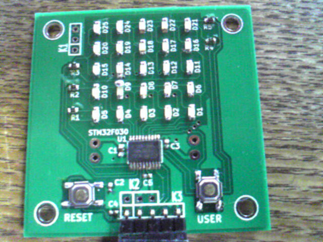
Here is a figure for FSM-55:
Top view of FSM-55:
+-------------------+
|O K1              O|
| []  * * * * *     |
| []  * * * * *     |
| []  * * * * *     |
|     * * * * *     |
|     * * * * *     |
|     U1+--+        |
|       +--+        |
|   K2[][][]  K3    |
| ()  [][][][][] () |
|RESET          USER|
|O    1 2 3 4 5    O|
+-------------------+
      | | | | |
      v v v v v
    RED       BLUE
And here is a figure for CN3 of ST-Link/V2:
CN3 of ST-Link/V2 (top view):
           /--> Pin 19 of CN3 of ST-Link/V2
           |
           \--[VAPP] 1 2 [VAPP] RED -----> Pin 1 of K3 of FSM-55
                     3 4
                     5 6
/---- BLACK [SWD-IO] 7 8
|/--- BLACK [SWDCLK] 9 10
||                  11 12
||                  13 14
||/-- BLACK [nRST]  15 16
|||                 17 18
|||        /--[VDD] 19 20 [GND] BLUE -----> Pin 5 of K3 of FSM-55
|||        |
|||        v
|||        Pin 1 of CN3 of ST-Link/V2
||v
||Pin 4 of K3 of FSM-55
|v
|Pin 3 of K3 of FSM-55
v
Pin 2 of K3 of FSM-55
Execution of the control program
Execute the control program from Command Prompt Window.
You need to be able to be execute the command of "ST-LINK Utility". For standard installation, PATH should include following path:
"\Program Files\STMicroelectronics\STM32 ST-LINK Utility\ST-LINK Utility"
Then, invoke following command line:
> ST-LINK_CLI -c SWD UR LPM -ME -P Desktop\hacker-emblem.hex -V after_programming -HardRst
which does:
- specify SWD UR LPM (SWD, Under Reset, Low Power Mode)
- Erase flash memory (-ME option)
- Program flash memory (-P option with filename)
- Verify flash memory (-V option)
- Assert hardware reset signal of target board
Note that -ME option is not required for the initial programming of the MCU.
- Expecter Behavior of the board
After hardware reset of the board, its 5x5 LED matrix demonstrates "Conway's Glider in Action". When you push USER button, all 25 LEDs emit light, and button released, it changes its mode to display scrolling text of "HAPPY HACKING!". Pushing RESET button, it starts from the beginning (of the Glider).
Test Result
Please record the test results:
The output of the control program. The last lines should be:
The file is downloaded successfully.

Verification...OK
Programming Complete.

Hard reset is performed.
The target board runs demonstration program of Glider (or not).
Pushing USER button all 25 LEDs emit light (or not), and releasing USER button, it changes its mode to scrolling "HAPPY HACKING!".
Pushing RESET button it starts from the beginning of Glider (or not).
All of above should be successful.
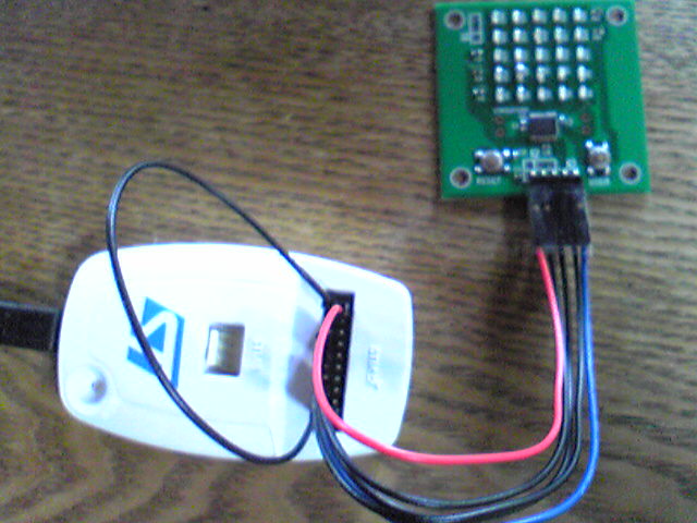
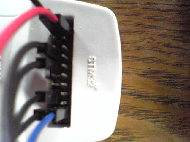
Example connection
Here are three photos of example connection by six wires and a connector (using a header pin, un-soldered).
Example session of the control program, ST-LINK_CLI.exe
Here is a example session (of version 3.3):
C:\Users\gniibe>"\Program Files\STMicroelectronics\STM32 ST-LINK Utility\ST-LINK Utility\ST-LINK_CLI.exe" -c SWD UR -ME -P Desktop\hacker-emblem.hex -V after_programming -HardRst

STM32 ST-LINK CLI v2.0.0
STM32 ST-LINK Command Line Interface

ST-LINK SN : 48FF6B064967535735220587

ST-LINK Firmware version : V2J21S4

Connected via SWD.

Connection mode : Connect Under Reset.

Device ID:0x444

Device flash Size : 16 Kbytes
Device family :STM32F031xx

Full chip erase...
Flash memory erased.

Loading file...

Some Segments are not shown.

Flash Programming:

  File : Desktop\hacker-emblem.hex

  Address : 0x08000000

Flash memory programming...

ロロロロロロロロロロロロロロロロロロロロロロロロロロロロロロロロロロロロロロロロロロロロロロロロアア 96%

Ram programming...

ロロロロロロロロロロロロロロロロロロロロロロロロロロロロロロロロロロロロロロロロロロロロロロロロロロ 100%

Reading and verifying device memory...

ロロロロロロロロロロロロロロロロロロロロロロロロロロロロロロロロロロロロロロロロロロロロロロロロロロ 100%

The file is downloaded successfully.

Verification...OK
Programming Complete.

Hard reset is performed.

C:\Users\gniibe>